cmstuber wrote:
I'm not completely stupid when it comes to basic electronics, I enjoy designing and building tube amps for fun, but i'm also not very smart, so please help me learn here...
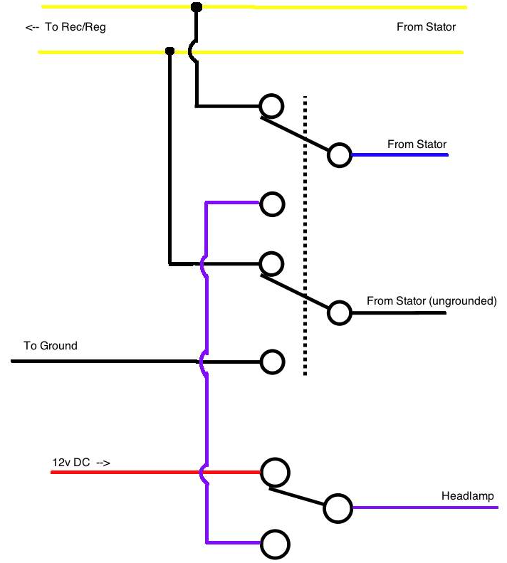
If at the point near the motor i'm getting 7v and at the load, the light, i'm getting 4.5v where is the current disappearing to? it must be traveling through some sort of resistance right because not all of that current is getting through? and if you say that resistance increases the load on the coils to output more power, the opposite seems to be happening here.
where are you taking your ground from in these measurements?
A key thing to get here is that this is *not* a voltage source system like you are used to seeing from a battery. this is a current source system. the important difference here is that in a voltage source based system, as you increase resistance, the power flowing thru the circuit decreases. in a current source based system, as the resistance increases, the power flowing thru the system increases, within the limits of the system to supply power.
to explain why is a whole 'nother 3 or 4 page thread i could dig up for you but suffice to say it's goofy and counter intuitive, and just the way the unregulated systems work.
Quote:
I understand what you are trying to say about where is the extra power going to come from. Right now I don't have any problems with battery SOC while having my phone plugged into my 12v socket on my DC side and my SIP Speedo also powers up on DC.
these are inconsequential loads compared to the 35w headlight. peak output of a cell phone charger is typically 500ma @ 5v, which is 2.5w. (at 5v, mind you). and that's the most it puts out, with a completely flat battery. as your battery charges, the rate of charge slows down, so if you have half full on your cell battery you could be drawing half (or less!) of the maximum rated output.
I also really doubt the SIP speedo is drawing more than a few hundred milliamps.
but put an ammeter across the circuit and you'll get a much better idea of what these loads are. you'll find them to be a pittance compared to a headlight.
Quote:
But if i'm getting 7 volts AC at idle at the stator, i'm definately getting much more at cruising speed of 6000rpms which if I put in new wiring to decrease resistance going into a rec/reg there might not be a problem. Just basic math says that i've lost 1.5x the current at the load, which means that at 6000rpm i'm producing at least 13v, not a ton but at least that's something that could be put back into the battery.
decreasing resistance may decrease the amount of power put out b the coil. yes, i know that sounds crazy, but yes, it is true.
as i asked before i'd need to see your methodology on where you're getting your ground from, but yours is not sound theory. voltage is (sort of) irrelevant here if you don't know current. your voltage will fluctuate depending on what the resistance of the circuit is, in accordance with watt's law.
to relate it to speed- it's like knowing the miles you traveled or the time it took you, but not both. each is meaningless without the other if you want to know the rate of speed.
Quote:
What sorts of voltage should i be seeing off this purple wire both at the motor and at the load at idle and at 6000rpms?
it depends immensely on the load.
the current is *somewhat* constant, but the voltage changes to match it, in the same way that the current output of a battery changes depending on how it is loaded.
Quote:
Again, not to be combative, I'm just trying to learn and understand so I can become more informed about my scoot.
no problem.
i'd just hate to see you completely rewire your bike and end up with a gutted harness and a nonfunctioning electrical system when the design isn't your problem; it's the faulty components.
Quote:
I agree that having a more modern Blue/Black stator would make this a whole hell of a lot easier, but then it wouldn't be worth the discussion either and I wouldn't take the time to learn something. For me, it's not just about having the the scoot 'done' is about the learning and exploring along with it, like a friend.
it'd only make it easier if you insist on rewiring your bike to all DC- witch in my opinion is the worst way you could go about fixing this fault.
Quote:
those vespatronic systems are super kick ass, i've been drooling over them for a while. Maybe someday when i fall into a swimming pool full of money i'll get it along with a pinasco cylinder, a PM evolution pipe, and some tubeless rims.
it's a bargain compared to what you're getting. it's not much more than what a complete stock ignition setup would cost you.
but again, with this DC idea you have i think you have a solution and you are trying to force your problem to fit it. borrow a known good flywheel and see if that makes a difference; if you can get a different stock stator try that as well.
diagnose and troubleshoot the stock setup as it is obviously not functioning as it should. My advice would be to spring for the varitronic as you may have more than $400 into this by the time you are done when you figure in parts and putting a price on your time and frustration. if you want one let me know; i an get you a good price on one.
cmstuber wrote:
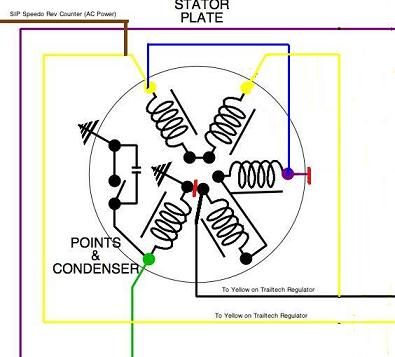
I also just had a thought, the purple wire, AC, is only half wave, if I floated the ground it would be full wave thus boosting the power output to be rectified.
no. if it went to a diode to convert to DC, it would be half wave. but as it is AC without any diode rectification, the full wave is being used to light the bulb.
full disclosure here- i'm a bit tired and am heading to bed so some of this might not be as clear as i intended it to be. i may re-read and edit in the morning.