I am installing a new engine in my 65 Vespa VBB. It is coming with a 12-volt stator and electronic ignition (no battery).
I know I need to replace all the 6-volt bulbs with their 12-volt equivalent.
Do I also need to replace the following items?
Foot Brake Switch
Main Handlebar Switch
Horn
Every electrical component on the scooter, including the harness, was replaced several years ago during the initial restoration.
With the conversion from the 6 volt to 12 volt can I safely increase the headlight wattage from 25/25 watts to 35/35 watts?
Finally, I think I have found 12 volt equivalent bulbs for everything except the speedometer. I'm looking for a 12 volt, 0.6 watt festoon bulb 6mm x 24mm. Does anyone know of a source for this bulb?
I appreciate your help
|
OP
|
|
|
UTC
quote
The closest one that meets your specs could be this one below:
https://www.bulbtown.com/6614F_Miniature_Bulb_SF6_6_Base_p/6614f.htm The biggest issue is you have to adapt it to fit in the speedometer, because it is 32 mm long and the end caps are not pointed. Now, If you can find a standard BUSS fuse holder for conventional glass fuses to replace the original bulb mount in the speedometer, it should work. Also, since it is rated at 14V, it should easily withstand the AC circuit varying outputs of your 12V stator. In your 12V circuit, if you multiply 12V X 0.05 A will give you .6W. Hope this helps.... |
|
|
UTC
quote
Oh, forgot about your other questions:
Yes, your 12V system should be just fine with the 35W bulb: https://www.ebay.com/itm/2pcs-BA20D-12V-35-35W-Motorcycle-Halogen-Headlight-Lamp-Bulb-Amber-A/363081092509?hash=item548951cd9d:g:AyEAAOSwEFhfPepg As far as switches and horn, being a no battery model, no other changes needed. |
|
OP
|
UTC
quote
Thanks for your reply but it just prompted more questions.
If I have a 6 volt horn won't the new 12 volt system burn it out? If you can keep it simple enough for a dummy to understand what difference does having or not having a battery have to do with the need to replace the main switch, foot brake switch & horn? |
|
Style Maven

'74 50s x3 '87 PK125XL '92 PK50XL2 Plurimatic - & - '58 AllState '68 Sprint '66(?) 125 Super '72 DanMotor 150 Super and '04 Bajaj LML hybrid
Joined: UTC
Posts: 10137 Location: seattle/athens |
UTC
quote
In my experience, just makes it louder, but I wouldn't be laying on the horn for long enuff to blow it up, maybe half a minute at most and never a problem.
Hold it in your hand and beep it some, does it seem to get hot? I bet it won't. All your switches are fine, they don't care if it's six or twelve volts. You may have to rewire or swap footbrake switch, but because of type, not voltage rating. Normal Closed or Normal Open depending on wiring. |
|
|
UTC
quote
65VBB2T wrote: Thanks for your reply but it just prompted more questions. If I have a 6 volt horn won't the new 12 volt system burn it out? If you can keep it simple enough for a dummy to understand what difference does having or not having a battery have to do with the need to replace the main switch, foot brake switch & horn? On these models, there is no voltage regulator. The basic regulation is achieved by the current flowing through all the bulbs and horn, as long as all the bulbs remain functional. The bulbs are lit when you switch them on via the switch, which stays in the "ON" position all the time, and lights up the bulb in the "OFF" position. This is completely opposite than on models with battery. Models with battery (like my PX) have separate DC (direct current) and AC circuits, with an electronic regulator designed specifically to handle separately their AC or DC circuits. Depending on the stator conversion you have, you may or may not need a specific AC-only regulator to handle your otherwise very simple circuits. You only have 4 bulbs and a horn in your bike to worry about. Like Voodoo says, your switches and wiring are fine for 12V , and the horn, being basically just an electromagnet, won't burn out with 12V with just a temporary push of its button. |
|
OP
|
UTC
quote
Engine Has Arrived and I'm Stumped
Well the new engine arrived yesterday for my 65 VBB2T (no battery). The engine came from the factory with a preinstalled 12 Volt stator. It also came with a CDI and voltage regulator. Neither was preinstalled nor came with instruction on how to connect them.
I've included a wiring diagram of my existing 6-volt setup. Once the old engine/stator/coil is removed I'll be left with the following seven (7) wires from the old harness at the junction box: Green Wire to horn Red Wire to terminal "M" on main handlebar switch Black Wire to ground 2 Blue Wires to rear stop light and foot brake switch 2 Yellow wires to the rear light & front pilot light I've included pictures of the new engine, CDI and voltage regulator below. As you can see the engine came with a coil preinstalled on the top of the engine. The preinstalled coil and the CDI both have spark plug wires. Should I remove the preinstalled coil and replace it with the CDI? There are two (2) connectors with five (5) wires coming out of the new stator in the new junction box. One connector is triangular shaped and has white, green & red wires. The other connector is side by side and has a blue and black wire. Of course, the connectors don't fit the terminals on the CDI, voltage regulator or existing wiring harness. At this point I'm baffled as to how to connect the wires from the stator to the CDI, voltage regulator, and existing wiring harness or if I even need to install the voltage regulator. I'll greatly appreciate any help I can get on how to wire the scooter. Hope someone can help. 
Original 6 Volt Wiring Diagram
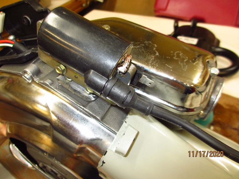
Factory Installed Coil
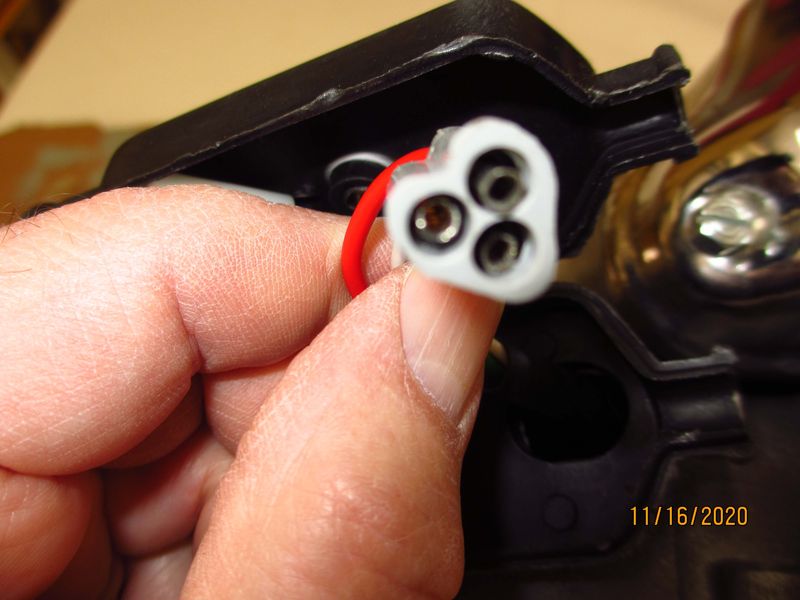
Stator Terminal
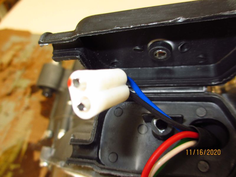
Stator Terminal

CDI
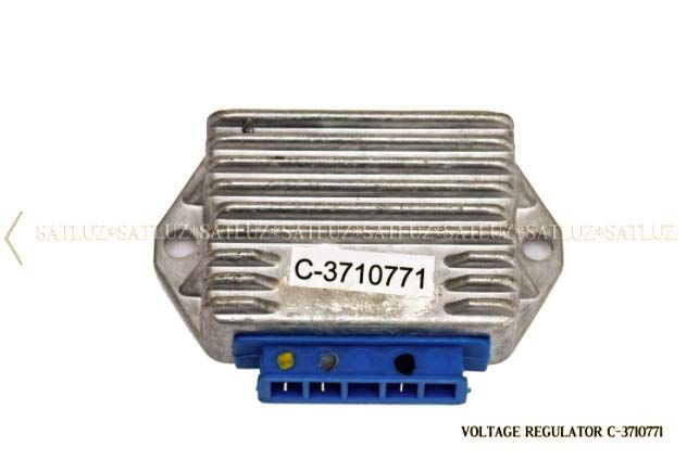
Voltage Regulator
|
 UTC
Ossessionato
2007 Stella 225
Joined: UTC
Posts: 3547 Location: Rochester, Minnesota |
|
|
|
UTC
quote
Re: Engine Has Arrived and I'm Stumped
I'm going to look up an old thread I had, it has wiring colors in it. Look up a p200 wiring diagram also to verify.
The bundle of three are ignition, You shouldn't need that coil, the blue cdi has one built in. There is a green wire from my kill switch to the cdi to kill the motor. It basically grounds the green terminal. Looks like your "Red Wire to terminal "M" on main handlebar switch" Looks like you red coming from your kill switch, is a ground going to terminal 2 on your coil for the ground, use for the green, when shutting off. These were mine, for the cdi White - Ground - already completed. Connect to white cdi Red - AC power to CDI - already completed. Connect to red cdi Green - Pickup coil signal - already attached. Connect to green cdi Green - Red Wire to terminal "M" on main handlebar switch Hook these up and the motor should start run and turn off. Blue and black AC power Blue - AC power from stator Black - is a ground to the chassis and motor. How do these get hooked to that regulator? Black is ground according to the wiring diagram. 65VBB2T wrote: Well the new engine arrived yesterday for my 65 VBB2T (no battery). The engine came from the factory with a preinstalled 12 Volt stator. It also came with a CDI and voltage regulator. Neither was preinstalled nor came with instruction on how to connect them. I've included a wiring diagram of my existing 6-volt setup. Once the old engine/stator/coil is removed I'll be left with the following seven (7) wires from the old harness at the junction box: Green Wire to horn Red Wire to terminal "M" on main handlebar switch Black Wire to ground 2 Blue Wires to rear stop light and foot brake switch 2 Yellow wires to the rear light & front pilot light I've included pictures of the new engine, CDI and voltage regulator below. As you can see the engine came with a coil preinstalled on the top of the engine. The preinstalled coil and the CDI both have spark plug wires. Should I remove the preinstalled coil and replace it with the CDI? There are two (2) connectors with five (5) wires coming out of the new stator in the new junction box. One connector is triangular shaped and has white, green & red wires. The other connector is side by side and has a blue and black wire. Of course, the connectors don't fit the terminals on the CDI, voltage regulator or existing wiring harness. At this point I'm baffled as to how to connect the wires from the stator to the CDI, voltage regulator, and existing wiring harness or if I even need to install the voltage regulator. I'll greatly appreciate any help I can get on how to wire the scooter. Hope someone can help. 
⚠️ Last edited by Christopher_55934 on UTC; edited 4 times
|
|
|
UTC
quote
I can't tell from your engine photo if there is this bracket at the rear of the engine:
http://www.scootermercato.com/Scooter-Parts/Ignition-Coils/164844 Probably not, since you have an ignition coil on top of the flywheel cover. You would not need that coil, since I am assuming that you are installing the CDI. The bracket in the link above is used, in fact, to attach the CDI to the engine. Now, the 3-way plug with white, red, and green wires connects to the CDI at the same colored terminals; you would have to cut off the plug and crimp on insulated 1/4" female connectors. The green outer most green connector on the CDI is the kill connection, which would have to connect to the red wire from the handlebar switch. The twin blue and black wires in the other plug from the stator would have to attach to the regulator via your existing junction box that is on your old engine that you would have to transfer to the new engine. You also need to find a convenient place to mount the regulator, usually inside the glove box wall on the other side. I have never owned a Vespa that old, though, so someone else would have to help you with the remaining connections, but it should be quite easy, because the regulator has just 3 connections: one input from the stator (I believe it is the blue wire), the black one from the stator goes to the black connection, and the 3rd one, which is the regulator output terminal (should be the yellow one from the junction box) which feeds the all the bulbs and horn. |
|
OP
|
UTC
quote
Thanks for taking the time to respond.
I spent time today reviewing your comments and various wiring diagrams and made a first attempt at preparing a "draft" wiring diagram for my scooter. I plan to clean it up and post it tomorrow. I hope if you have time you will review it and provide feedback. |
|
OP
|
UTC
quote
Below is my attempt at laying out the wiring for my CDI & voltage regulator installation on my 65 VBB2T. I prepared it by referring to the notes you were kind enough to provided and the Vespa P200E wiring diagram also below.
The standalone terminal on the voltage regulator is either black or dark blue. I assumed it is black and connected the black wire from the stator to it based on the P200E wiring diagram. Does this seem correct for my installation? The other two terminals are not color coded and I don't know if it makes a difference which wire is connected to which of the two terminal on the regulator. Does it? Please review my wiring diagram and provide feedback. Thanks 

|
|
UTC
Ossessionato
2007 Stella 225
Joined: UTC
Posts: 3547 Location: Rochester, Minnesota |
|
|
|
UTC
quote
65VBB2T wrote: Below is my attempt at laying out the wiring for my CDI & voltage regulator installation on my 65 VBB2T. I prepared it by referring to the notes you were kind enough to provided and the Vespa P200E wiring diagram also below. The standalone terminal on the voltage regulator is either black or dark blue. I assumed it is black and connected the black wire from the stator to it based on the P200E wiring diagram. Does this seem correct for my installation? The other two terminals are not color coded and I don't know if it makes a difference which wire is connected to which of the two terminal on the regulator. Does it? Please review my wiring diagram and provide feedback. Thanks |
|
UTC
Ossessionato
2007 Stella 225
Joined: UTC
Posts: 3547 Location: Rochester, Minnesota |
|
|
|
UTC
quote
AC Horn button on the handlebar switch - role in the circuit
This is why I was confused, leaving this here helps explain the original wiring, in the P200. Looking at the P200 wiring diagram, the blue wire from the stator goes to a switch in the handle bars, that switch is normally closed and continues out the other side as yellow. That yellow wires goes to the regulator, and is how AC is getting to the regulator. Connecting the blue stator output wire to the yellow regulator input connection, should supply power to the regulator. Then you should be able to connect your original scooter blue and yellow wires, to the regulator green connection to supply regulated voltage. Leave the horn disconnected for now. Random thoughts on the horn and green coil wire: The switch in your scooter drawings is incomplete compared to what I'm used to seeing, it doesn't show connection points. I don't know what connects to what when a switch is pressed or flipped or whatever. If you look at the horn button on the P200 diagram you can see the switch connection between the blue and yellow wires. The AC horn looks like the big? It was never hooked up to the regulator in the P200, guessing it draws to much current to go through the regulator without burning it up. Your scooter horn green wire was connected directly to a coil, from what I can see. I have no idea about the white wire. You may find other things were powered by that green coil wire and need to hook it up to the regulator also if something else doesn't work. The unknown is if you press the horn button, will the regulator Be able to handle the current draw. |
|
|
UTC
quote
I looked at other Vespa models electrical diagrams from the '60s and '70s, as well as the P200E diagram shown above; It seems to me that the P 200E diagram is really not the best reference to use to make the conversion work.
The P 200E has turn signals; the AC flasher that powers them is connected to the regulator. Perhaps, the very rare P series diagram (no turn signals) may be a better guide, but I have not been able to find it online. It appears to me that to simply go from the 6V to 12V stator, the regulator would be unnecessary, in this case, since the VBB does not have signals. As long as all the bulbs are changed to 12V type, the blue wire from the stator could be connected to the horn switch and to the stop light via the brake pedal switch, and the yellow wire from the other horn switch terminal could go to the tail light, front pilot light, speedo light, and headlight. The black wire from the stator, of course, would attach where the existing chassis/earth connection. I would agree to leave the horn disconnected while making all connections and test the system first with the engine running, before connecting it to verify its operation. |
|
|
UTC
quote
I think one of these should get you started it says for 6V but it could be used for 12V. You should be good to run yellow to regulator unregulated, yellow out regulated.
pdf
522kb
pdf
522kb
|

|
OP
|
UTC
quote
Guys
I haven't been ignoring you. I've just been trying to digest what has been posted. Let me ask two questions. 1. Since the engine came with a 12 volt stator installed and no points I'm just wondering what was the logic of it shipping it with a coil mounted on it? Connecting the CDI seems straight forward. The rest of the wiring is the problem. 2. Is installing the Voltage Regulation optional? If yes what are the pros and cons? |
|
|
UTC
quote
sp949 wrote: It appears to me that to simply go from the 6V to 12V stator, the regulator would be unnecessary, in this case, since the VBB does not have signals. As long as all the bulbs are changed to 12V type, the blue wire from the stator could be connected to the horn switch |

|
|
UTC
quote
These ready-built engines can be installed in most Vespas. So, maybe the buyer does not want the 12V stator, and wants to transfer the old 6V stator with points, which would require the external coil to complete the ignition system. The entire 12V stator + regulator is designed as an upgrade to retrofit all models including those that came with turn signals and more powerful bulbs.
I almost bought one of these, but I opted to get my PX150E rebuilt instead. I wanted to keep the electric starter and the auto lube system: these engines are not equipped for these options. As far as the regulator, the one that you show above is rated at 96 watts, which tells me that the 12V stator is capable of at least the same power. I don't think you need it, as long as you wire the stator so that all the 12V bulbs act as the regulator in the circuit. The system is elegantly simple, but, with simplicity, there are, of course, limitations. As soon as the first bulb blows, the next bulb in the chain blows shortly due to the increase of resistance. Basically, the regulator output makes a loop through the horn button, the brake switch, and all the bulbs, not allowing the total resistance of the circuit to increase to the point of failure. Notice that the system has no fuses; no need for them, as long as all the bulbs work. |
|
UTC
Ossessionato
2007 Stella 225
Joined: UTC
Posts: 3547 Location: Rochester, Minnesota |
|
|
|
UTC
quote
Put the regulator in, no need to worry about a balanced system, the regulator will keep the voltage at an acceptable level, blown bulb or not. 60 years ago regulator technology wasn't great it's a lot better now.
If you bought a pre packaged LML motor, the cdi is a separate part on a LML motor so you need the coil. The cdi box is on the other side by the battery. That blue box is a Ducati style cdi, which has everything in one convenient package. |
|
OP
|
UTC
quote
I'm still chewing on this.
Can someone look at the 1st wiring diagram I posted for my VBB150 and tell me if power is being fed from the coil to the main switch on the handlebars by the red wire (terminal M - kill switch)? If yes, what device(s) does it powering? Thanks |
|
UTC
Ossessionato
2007 Stella 225
Joined: UTC
Posts: 3547 Location: Rochester, Minnesota |
|
|
|
UTC
quote
65VBB2T wrote: I'm still chewing on this. Can someone look at the 1st wiring diagram I posted for my VBB150 and tell me if power is being fed from the coil to the main switch on the handlebars by the red wire (terminal M - kill switch)? If yes, what device(s) does it powering? Thanks If you have a multimeter set it to check resistance, attach one lead to ground, the other to the lead to the wire going to the switch, it should be normally open. When you press the button the resistance should go to "0", most like about 1 ohm if you have good connections. |
|
Molto Verboso

GL, PK, PE200 with hack, Sears Rust Badge
Joined: UTC
Posts: 1347 Location: Deep in the heart of Texas |
UTC
quote
I've read some of this post but bare with me if I repeat some of things mentioned earlier.
65VBB2T wrote: I'm still chewing on this. Can someone look at the 1st wiring diagram I posted for my VBB150 and tell me if power is being fed from the coil to the main switch on the handlebars by the red wire (terminal M - kill switch)? The power came from the yellow and green wires. The stator does two things; provide spark and provide power for lights. Neither interact with one another outside the stator. The way lighting electricity is flowing changes with a 12v conversion and you will need to add wires and tape up unused wires. You will also need a multimeter to verify wires. The three prong regulator is best used for these types of conversion. On that type of regulator. there is one prong for power in, other is power out (doesn't mater which one) and there is a dedicated ground prong. You will need to get connectors that will fit your regulator prongs. Depending on where you place your regulator, you will need to get additional wires, too. The stator wires may not be long enough to reach the regulator. Spark power from Stator: Based on your homemade wiring diagram, the wiring for the spark seems correct. The red wire to the handle bar is only used to ground that circuit and turn the motor off. No power for lighting what so ever goes to that wiring. You can hook up those wires and no other wires to see if the motor provides a spark or crank. Lighting power from Stator to regulator: Looking at your homemade diagram, the black ground wire from stator to regulator seems correct. The blue wire from the stator is the power wire and should go to one of the regulator slots. The other slot is for regulated steady 12v power for the lights and should go out back to the junction box. Add another wire from that regulator slot back to junction box. Lighting power from regulator to junction box: 1. The new power wire form the regulator connects to the green horn wire and the blue wire to the brake switch. You can just screw that power wire from the regulator to a screw in the junction box with those green and blue wires. Make sure the blue wire is going to the brake switch and not the brake light. 2. Pull the 6v brake switch and change to a 12v brake switch. Tape off old black ground wire that went to the old brake switch. That wire is not connected to anything now. You will need to add another wire that goes from the brake switch back to the junction box. The brake switch should now have a connection from the power wire at the junction box and a new wire for power going back to the junction box. That new power wire from the brake switch connects at the junction box with the other blue power wire that goes to the brake light. 3. You will need to connect the yellow wires to one screw at the junction box. Before the power for the yellow wire came directly from the stator. With a 12v conversion the power is coming directly from the handlebar. Power at the handlebar switch: The power to the handlebar switch is coming through the horn via the junction box. There's a way too change over the handlebar switch from 6v to 12v but it requires soldering wires and changing the horn connection. A beginner should just buy a 12v handlebar switch. When you get the 12v switch or want to try to convert your 6v switch use this diagram to connect the wires correctly https://studylib.net/doc/18653785/beedspeed-conversion-wiring-diagram-for-rally--sprint. |
|
OP
|
UTC
quote
All
First, my thanks to all that took the time to respond to my query and I want to wish each of you and your families a safe, happy and especially HEALTY holiday. I found a wiring diagram that I think shows how to make the connections. I'm going to post it and a cleaner version of the original Vespa 150 wiring diagram in case you want to flip between them. The one area I'm a bit unsure of is it appears that the yellow wire from the voltage regulator (VR) gets connected to the green wire to the horn and the 2 yellow wires running between the rear light and terminal 4 on the switch (Join). It seems to me that if I connect the three yellow wires together the rear light will be on all the time. The other significant change is the black wire to the brake switch is replaced with a green wire directly from the VR. Rowdyc - In the next day of so I'll draw out what you describe in your narrative. I don't think it will be to dissimilar from the Atomic wiring diagram. I'm still unclear if I MUST replace the main switch or at the very least modified it or if doing anything with the switch is optional? 

|
|
Molto Verboso
GL, PK, PE200 with hack, Sears Rust Badge
Joined: UTC
Posts: 1347 Location: Deep in the heart of Texas |
UTC
quote
Just use that Atomic diagram you've found. Its basically the same of what I tried to describe. You can see where you need to add wires.
65VBB2T wrote: All The one area I'm a bit unsure of is it appears that the yellow wire from the voltage regulator (VR) gets connected to the green wire to the horn and the 2 yellow wires running between the rear light and terminal 4 on the switch (Join). 65VBB2T wrote: All The other significant change is the black wire to the brake switch is replaced with a green wire directly from the VR. 65VBB2T wrote: All I'm still unclear if I MUST replace the main switch or at the very least modified it or if doing anything with the switch is optional? https://studylib.net/doc/18653785/beedspeed-conversion-wiring-diagram-for-rally--sprint. Good luck! |
|
OP
|
UTC
quote
Rowdyc
What do you make of the circle that say "Join" around the yellow wires in the junction box? If they aren't connected how does power get to the front lights Thanks for your help. |
|
|
UTC
quote
First you should understand how the system works and adapt to your scooter.
The stator does two things; provide spark and provide power for lights. Neither interact with one another outside the stator. The three prong regulator is best used for these types of conversion. On that type of regulator. there is one prong for power in, other is power out (doesn't mater which one) and there is a dedicated ground prong. The red wire to the handle bar is only used to ground that circuit and turn the motor off. No power for lighting what so ever goes to that wiring. You can hook up those wires and no other wires to see if the motor provides a spark or crank. The other slot is for regulated steady 12v power for the lights and should go out back to the junction box. Add another wire from that regulator slot back to junction box. Pull the 6v brake switch and change to a 12v brake switch. 12v conversion the power is coming directly from the handlebar. Power at the handlebar switch: The power to the handlebar switch is coming through the horn via the junction box. There's a way too change over the handlebar switch from 6v to 12v but it requires soldering wires and changing the horn connection. A beginner should just buy a 12v handlebar switch. When you get the 12v switch or want to try to convert your 6v switch use this diagram to connect the wires correctly https://studylib.net/doc/18653785/beedspeed-conversion-wiring-diagram-for-rally--sprint.[/quote] Sorry to interject, as I don't have any skin in this game, but: I am assuming this regulator only regulates AC power, without rectifying it to DC, since it is meant only for no-battery operation. But why replace the switches? Aren't they NC type (contacts bridged on resting position) Are the suggested 12V switches NO (contacts not bridged in resting position)? AFAIK, all electrical switches are limited only by amps, not voltage. As I understand it, since the upgrade to 12V still remains AC type, there should be no need to replace the switches, especially considering that more volts will not result in higher amp flow. The last diagram shown seems completely correct to me.. My reason for my curiosity is that I have been looking to buy a no-battery Sprint or GL Vespa, if I could find one at a reasonable price, and these models have the same electrical system as the OP VBB model. |
|
Molto Verboso
GL, PK, PE200 with hack, Sears Rust Badge
Joined: UTC
Posts: 1347 Location: Deep in the heart of Texas |
UTC
quote
65VBB2T wrote: Rowdyc What do you make of the circle that say "Join" around the yellow wires in the junction box? If they aren't connected how does power get to the front lights Thanks for your help. With this setup, power from the regulator goes to a switch and that switch directs the power to the next component. You have two switches (rear brake and headset) which requires two wires from the regulator. None of the regulated power should go directly to a light before going to a switch. |
|
UTC
Ossessionato
2007 Stella 225
Joined: UTC
Posts: 3547 Location: Rochester, Minnesota |
|
|
|
UTC
quote
rowdyc wrote: 65VBB2T wrote: Rowdyc What do you make of the circle that say "Join" around the yellow wires in the junction box? If they aren't connected how does power get to the front lights Thanks for your help. With this setup, power from the regulator goes to a switch and that switch directs the power to the next component. You have two switches (rear brake and headset) which requires two wires from the regulator. None of the regulated power should go directly to a light before going to a switch. |
⬆️ About 3 months elapsed ⬇️
|
OP
|
UTC
quote
I got the scooter running so I want to thank everyone that took the time to respond to my post and share the wiring configuration that worked for me for the benefit of someone that may find this post in the future.
First, a brief summary, I purchased a new engine for my 65 Vespa VBB2T which converted it from a 6-volt scooter with points and condenser to a 12-volt scooter with electronic ignition. The engine swap was more involved than I expected. I ended up installing a CDI, voltage regulator, replacing and rewiring the brake switch, replacing the main switch on the handlebar, installed a 12-volt horn and replaced the light bulbs. On my scooter I needed a brake switch that completed the circuit when the brake pedal was pushed forward which allowed the switch plunger to move out. The only bulb I had difficulty finding in 12-volt was the festoon for the speedo. I only found one place in this country that sold a 6 x 28 mm long bulb and it was 1.2 watts not the original 0.5 watts. I had to purchase 10 of them so I have extra if you are in need. Main Switch from Beedspeed - 12-Volt Conversion (closer) Part # DB12990 picture below Horn 12-Volt from Scooter Mercato Part # 12VHORNAC-Shell Festoon Bulb for Speedo from Interlight Part # WW-3VJ6-1 On the advice of someone that responded in an earlier message I purchased an inexpensive 12-volt battery so I could test everything EXCEPT the horn without starting the engine. So, onto the wiring which was the original purpose of this thread. Below is the 6-volt wiring diagram of the scooter before the conversion so you can see what I started with. Followed by the Atomic" wiring diagram I ended up with but with modifications to the connections at the main switch as noted below. Terminal #1 - Tape up and do not use the black wire Terminal #3 - The 2 green wires from the horn Terminal #4 - 2 yellow and the blue speedo wire Terminal #6 - Brown wire to the headlight Terminal #7 - Purple wire to headlight Terminal #8 - White wire from horn. Terminal above the 8 in the picture Terminal #M - Red wire for the kill switch (terminal next to the notch on the right side of the switch. Ignore the oval at the junction box the says "join". Image my delight after trying to get the scooter to run (old engine) for several years when the new engine fired up. Then image me laughing like hell when I couldn't get it to shut off. I had to pull the sparkplug wire. After replacing the main switch, I elected to put the old cover back on because it had a better finish. Well, it turns out the kill switch contacts built into the inside of the two covers were slightly different. The kill switch functioned correctly once the cover was replaced with the one that came with the new main switch. I don't think the saga is over for this scooter because it is more difficult to get started then it should be which will probably end up with another thread. Hope this will end up helping someone. 
Beedspeed Switch 12-Volt Switch

Original 6- Volt Wiring Diagram

12-Volt Wiring Diagram
|
|
|
UTC
quote
Thanks so much for posting this. I am in a very similar situation - P200 12V engine going in a (no battery) VBB still in a state of assembly - and am indebted to you for these pointers.
|

⬆️ About 2 months elapsed ⬇️
|
OP
|
UTC
quote
If you scroll back through this thread you will see that my new engine came with a HT coil preinstalled and a separate CDI. I installed the CDI and removed the HT coil on the asspmption the HT coil was built into the new CDI and was not needed.
The new engine has always been hard to start and while the spark seems adequated I'm not sure it is as robust as it should be. I came across a document today, that I think is 20 - 25 years old, that clearly shows a separate CDI and HT coil installed on a scooter. The CDI was connected to the HT coil and the spark plug wire was coming out of the HT coil. I'm I correct to assume that enhancements led to the inclusion of the HT coil in the modern CDI's and I was correct in removing the HT coil? |
Modern Vespa is the premier site for modern Vespa and Piaggio scooters. Vespa GTS300, GTS250, GTV, GT200, LX150, LXS, ET4, ET2, MP3, Fuoco, Elettrica and more.

Shop on Amazon with Modern Vespa
Modern Vespa is a participant in the Amazon Services LLC Associates Program, an affiliate advertising program designed to provide a means for sites to earn advertising fees by advertising and linking to amazon.com
Modern Vespa is a participant in the Amazon Services LLC Associates Program, an affiliate advertising program designed to provide a means for sites to earn advertising fees by advertising and linking to amazon.com
[ Time: 0.0112s ][ Queries: 4 (0.0033s) ][ live ][ 343 ][ ThingOne ]